The Honeywell TH5220D1029 is a non-programmable digital thermostat designed for reliable temperature control in various HVAC systems. It offers a user-friendly interface and clear display for easy operation.
1.1 Overview of the Honeywell TH5220D1029
The Honeywell TH5220D1029 is a non-programmable digital thermostat designed for reliable temperature control in single-stage and multi-stage heating and cooling systems. Part of the FocusPRO series, it offers a user-friendly interface with a clear, backlit display for easy readability. This thermostat is compatible with 24 VAC systems, 750 mV heating systems, and heat pumps, making it versatile for various HVAC setups. Its simplicity and durability ensure long-term performance, providing precise control for maintaining desired indoor temperatures efficiently.
1.2 Features of the Honeywell TH5220D1029
The Honeywell TH5220D1029 features a large, backlit display for easy temperature adjustments and offers one-touch controls for simplicity. It supports selectable changeover modes, allowing manual or auto switching between heating and cooling. The thermostat includes built-in compressor protection to prevent damage and auxiliary heat control for heat pump systems. With options for AC or battery power, it ensures reliability during power outages. Additionally, it offers fan control settings and system configuration options, making it adaptable to various HVAC configurations while ensuring efficient and consistent temperature management.

Pre-Installation Checklist
Ensure the package includes the thermostat, wall anchors, screws, batteries, and manual. Verify required tools like a Phillips screwdriver are available. Disconnect power before starting.
2.1 Package Contents
The Honeywell TH5220D1029 package includes the FocusPRO digital thermostat, wall anchors, mounting screws, and AA alkaline batteries. Additionally, the package contains an operating manual for guidance. Ensure all items are present before starting the installation process to avoid delays. Verify the wallplate is attached to the back of the thermostat for proper mounting. These components are essential for a successful and straightforward installation. Make sure to review the manual for specific instructions tailored to your system type.
2.2 Required Tools and Supplies
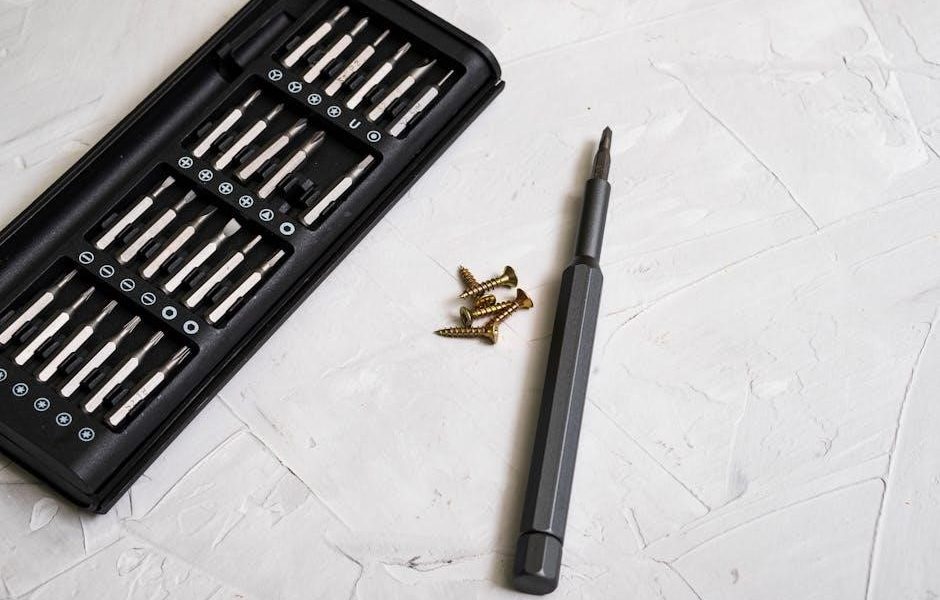
To install the Honeywell TH5220D1029 thermostat, you will need a No. 2 Phillips screwdriver for mounting and wiring connections. Use 18- to 22-gauge thermostat wire for proper system connectivity. Shielded cable is not required for this installation. Additional supplies may include wall anchors and screws, though these are typically provided in the package. A voltage tester is recommended to ensure power is off before starting work. Optional tools like a drill may be needed for wall hole preparation. Ensure all necessary items are available to facilitate a smooth installation process.
2.3 Safety Precautions
Disconnect power to the HVAC system before starting installation to avoid electrical shock or equipment damage. Ensure the system is completely powered down. Handle wires carefully to prevent short circuits. If replacing a mercury-containing thermostat, dispose of it properly by contacting local waste management authorities. Avoid installing near areas exposed to direct sunlight, moisture, or extreme temperatures, as this may affect performance. Always follow the manufacturer’s guidelines and safety instructions to ensure a safe and successful installation process.

Installation Process
The installation involves wallplate mounting, wiring connections, and thermostat attachment. Ensure proper alignment and secure fastening. Follow the step-by-step guide for a successful setup.
3.1 Wallplate Installation
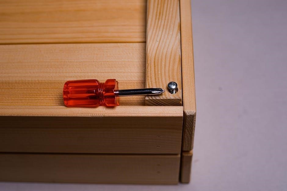
Begin by removing the wallplate from the thermostat. Insert a finger into the wire hole and gently pull to detach. Mount the wallplate to the wall using the provided screws and anchors. Ensure it is level and securely fastened. This step is crucial for proper thermostat alignment and functionality. Follow the manufacturer’s instructions carefully to avoid damage or installation issues.
3.2 Wiring the Thermostat
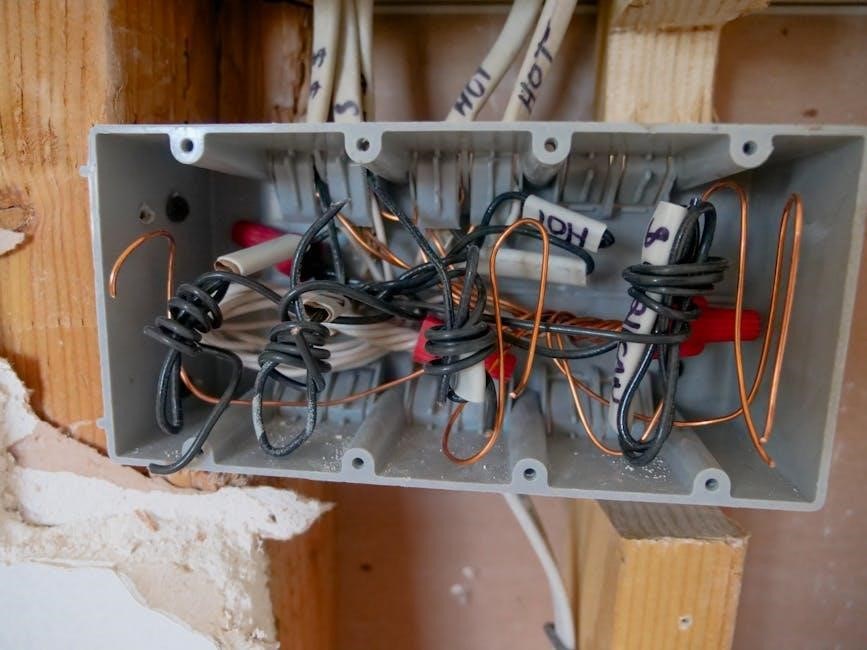
Disconnect power before wiring. Remove the jumper between R and Rc for two-transformer systems. Connect wires to corresponding terminals: R (24V), W (heat), Y (cool), C (common), and L (emergency heat). Use 18-22 gauge wire. For heat pumps, configure W/O/B terminal as needed. Ensure proper connections to avoid system issues. Follow wiring diagrams in the manual for accurate setup. Double-check all connections before restoring power to ensure safe and correct operation.
3.3 Mounting the Thermostat
Align the wallplate with the thermostat’s tabs and gently push until it snaps securely. Use wall anchors for uneven surfaces. Ensure the thermostat is level and firmly mounted. Remove the wallplate before drilling holes, then reinstall it after securing with screws. Mounting must be stable to prevent damage. Follow the manual’s alignment guide for proper installation. Ensure all tabs click into place for a secure fit. Double-check leveling to maintain accurate temperature readings and system performance. Proper mounting ensures reliable operation and longevity of the thermostat.

Terminal Designations and Wiring Diagrams
This section explains terminal labels and wiring diagrams for the TH5220D1029, detailing connections for R, Rc, C, W, and L terminals across different HVAC systems.
4.1 Understanding Terminal Designations
Understanding terminal designations is crucial for proper installation. The TH5220D1029 terminals include R (24VAC power), Rc (cooling), W (heat), Y (compressor), and C (common). The L terminal is for heat pump reset. In single-transformer systems, a jumper connects R and Rc, while in dual-transformer systems, it’s removed. The C terminal is optional with battery power. Correct wiring ensures system functionality and safety, preventing electrical hazards and equipment damage.
4.2 Wiring Diagrams for Different Systems
Wiring diagrams vary based on system type. For 1H/1C systems, connect R to Rc with a jumper. Heat-only systems use R and W. Heat pumps require connections to O/B and L terminals. Ensure correct wiring to match system configurations, preventing operational issues. Always follow the manufacturer’s guide for specific setups to ensure safety and functionality. Correct wiring is essential for optimal performance and to avoid damage to the thermostat or HVAC system. Refer to the manual for detailed diagrams tailored to your system.
Power Options and Mounting
The Honeywell TH5220D1029 supports both AC power and battery operation. It can be powered by 24 VAC or AA alkaline batteries for backup during outages. Secure mounting ensures stability.
5.1 AC Power Configuration
For AC power, connect the common wire to the C terminal. In single-transformer systems, a jumper links R and Rc; remove it for two-transformer setups. Ensure 24 VAC power is supplied, and avoid cycling the compressor too quickly to prevent damage. This configuration is ideal for systems requiring constant power, ensuring reliable operation and display functionality. Always disconnect power before wiring to avoid electrical hazards, as indicated in the manual.
5.2 Battery Power Configuration
The Honeywell TH5220D1029 can be powered by two AA alkaline batteries, providing backup power during outages. Batteries can be replaced without removing the thermostat from the wall. In battery mode, the C terminal is optional, allowing operation without a common wire. This configuration is ideal for systems where AC power is unavailable or unreliable. The thermostat maintains functionality, ensuring continuous temperature control. Always use fresh batteries to avoid display issues. This setup is convenient for installations without a constant power source, offering reliability and ease of use.
5.3 Mounting the Thermostat Securely
To mount the Honeywell TH5220D1029, align the wallplate with the thermostat’s tabs and gently push until it snaps into place. Ensure the thermostat is level and secure to prevent uneven operation. Use the provided wall anchors and screws for a sturdy installation. Avoid locations exposed to direct sunlight, drafts, or extreme temperatures to maintain accurate temperature readings. Proper mounting ensures reliable performance and longevity of the device. Always follow the manufacturer’s guidelines for optimal installation and functionality.
Installer Setup and System Configuration
Configure the Honeywell TH5220D1029 to match your HVAC system, including system type, changeover valve settings, and fan control. Adjust settings for optimal performance and compatibility.
6.1 System Type Configuration
The Honeywell TH5220D1029 requires system type configuration to ensure compatibility with your HVAC setup. Select options such as 1-Heat/1-Cool, 2-Heat/1-Cool, or heat pump systems. Proper configuration ensures accurate temperature control and efficient operation. Use the installer setup menu to choose the correct system type, ensuring all features align with your equipment. This step is crucial for optimal performance and to avoid potential issues with heating or cooling functions. Refer to the manual for specific settings and guidance.
6.2 Changeover Valve Settings
The Honeywell TH5220D1029 allows configuration of the changeover valve to match your HVAC system. Set the changeover valve to ‘O’ for cooling or ‘B’ for heating, depending on your system type. Proper configuration ensures the thermostat operates correctly, preventing issues like simultaneous heating and cooling. Incorrect settings can lead to system performance problems. Always refer to the installation manual for specific guidance on configuring the changeover valve for your particular setup to ensure optimal functionality and avoid operational errors.
6.3 Fan Control Settings
The Honeywell TH5220D1029 thermostat includes fan control settings to manage your HVAC system’s fan operation. In the Installer Setup, configure Function 3 to choose between ‘Auto’ or ‘On’ modes. The ‘Auto’ mode operates the fan only during heating or cooling cycles, while ‘On’ mode runs the fan continuously for improved air circulation. Proper fan control ensures efficient system performance and can help maintain consistent indoor air quality. Always align the fan control setting with your HVAC system type to optimize functionality and comfort.
System Testing
Test the heating, cooling, and fan systems to ensure proper operation. Verify thermostat responses and check for any issues like delayed starts or incorrect cycling.
7.1 Testing Heating and Cooling Systems
To test the heating system, set the thermostat to Heat mode and adjust the temperature above the current room temperature. Ensure the heating system activates and warms the space. For cooling, switch to Cool mode and lower the setpoint below the room temperature. Verify the cooling system starts and cools effectively. Check for proper cycling and consistent temperature maintenance. If issues arise, consult the troubleshooting section or adjust settings as needed to ensure optimal performance.
7.2 Testing Fan Operation
To test the fan operation, set the fan switch to the On position and verify that the fan runs continuously. If the fan does not turn on, check the Installer Setup (Function 3) to ensure the fan control is configured correctly for your system type (e.g., Gas/Electric or Heat Pump). In Auto mode, the fan should only operate during heating or cooling cycles. If issues persist, consult the troubleshooting section or adjust the fan settings as needed to ensure proper airflow and system performance.
7.3 Verifying System Response
After testing individual components, verify the system’s overall response. Set the thermostat to Heat and ensure the heating system activates. Repeat for Cool mode to confirm proper operation; Check the transition between modes to ensure smooth switching without delays. During testing, compressor protection may be bypassed to allow rapid cycling. Once testing is complete, ensure compressor protection is re-enabled to prevent equipment damage. This step ensures the thermostat and HVAC system function seamlessly together.

Configuration Options
The Honeywell TH5220D1029 offers customizable settings, including changeover modes, compressor protection, and auxiliary heat control, allowing tailored operation for different HVAC systems and user preferences.
8.1 Changeover Modes (Auto/Manual)
The Honeywell TH5220D1029 features Auto and Manual changeover modes. In Auto mode, the thermostat automatically switches between heating and cooling based on the set temperature, maintaining a 3-degree deadband. This mode is ideal for climates requiring frequent transitions. Manual mode allows users to manually select heating or cooling, offering flexibility for specific conditions. The 3-degree separation ensures efficient operation, preventing simultaneous heating and cooling. This feature enhances comfort and energy efficiency, adapting to user preferences and system requirements. Proper configuration is essential for optimal performance.
8.2 Compressor Protection Settings
The Honeywell TH5220D1029 includes a compressor protection feature to prevent damage from rapid restarts. This setting enforces a minimum off-time, ensuring the compressor rests between cycles. During testing, this feature is bypassed to avoid equipment damage. The thermostat flashes messages like “Cool On” or “Heat On” during the wait period. Compressor protection is crucial for both AC and heat pump systems, preventing short cycling that can lead to wear and tear. This feature is pre-configured but can be adjusted via Installer Setup for specific system requirements, ensuring optimal performance and longevity.
8.3 Auxiliary Heat Control
The Honeywell TH5220D1029 offers auxiliary heat control for systems with heat pumps. It operates in two modes: Comfort and Economy. In Comfort mode, auxiliary heat activates to prioritize temperature consistency, while Economy mode delays auxiliary heat to reduce energy use. The thermostat adjusts based on system performance and temperature changes. Auxiliary heat is typically used when the heat pump cannot maintain the setpoint. Settings are configurable in Installer Setup, allowing customization to balance comfort and energy efficiency according to specific needs and system requirements.

Troubleshooting Common Issues
Common issues include temperature settings not changing, system non-response, or fan malfunctions. Check settings, wiring, and power. Reset or replace batteries if necessary. Ensure proper installation and configuration for optimal performance. Refer to the manual for detailed solutions and safety precautions.
9.1 Temperature Settings Not Changing
If the temperature settings on your Honeywell TH5220D1029 thermostat are not changing, ensure the system is powered correctly. Check for loose or incorrect wiring connections, especially between the R, Rc, and C terminals. Verify that the thermostat is properly mounted and batteries are fresh if using battery power. Also, confirm that the system type and changeover valve settings are correctly configured during installation. If issues persist, reset the thermostat by removing batteries or disconnecting power temporarily. Always refer to the installation manual for detailed troubleshooting steps specific to your system configuration; This ensures safe and effective resolution without causing further complications. Proper setup and regular maintenance can prevent such issues, providing seamless temperature control and enhancing overall system efficiency. Additionally, ensure that the temperature setpoints are within acceptable ranges and that there are no conflicts in the system’s operating parameters. By addressing these factors, you can restore functionality and maintain consistent indoor comfort.
9.2 Heating or Cooling System Not Responding
If the heating or cooling system fails to respond, verify that the thermostat is properly powered. Check for correct wiring connections, especially between the R, C, and W terminals. Ensure the system type (heat pump, furnace, etc.) is correctly configured in the Installer Setup. Also, confirm that the thermostat is set to the correct mode (Heat, Cool, or Auto). Check the user controls to ensure the desired temperature setpoints are properly adjusted. If the issue persists, reset the thermostat by removing batteries or disconnecting power temporarily. Always ensure the system is compatible with the thermostat’s settings for proper operation. Addressing these factors can restore system response and maintain reliable performance. Regular checks and proper configuration are essential to avoid such issues and ensure optimal comfort.
9.3 Fan Issues
If the fan is not operating correctly, check the fan control settings in the Installer Setup (Function 3). Ensure the fan is configured to match the system type, such as “Auto” or “On.” Verify wiring connections, particularly the G (fan) terminal. If the fan runs continuously, ensure it is not in “Test” mode. Check for blockages in air vents or filters that could restrict airflow. Ensure the fan setting is properly aligned with the system mode (Heat, Cool, or Off). If issues persist, consult the Installer Setup for additional configuration options or reset the thermostat by removing batteries temporarily. Proper fan operation is crucial for system efficiency and comfort. Always ensure settings and wiring align with the installed HVAC system for reliable performance.
9.4 Heat Pump Issues
If the heat pump is not functioning correctly, ensure the changeover valve settings (O/B) in Installer Setup (Function 2) are properly configured. Verify wiring connections, especially the L terminal, which activates during Emergency Heat. If the heat pump produces cool air in heat mode or warm air in cool mode, check the system configuration and wiring diagrams. Ensure the heat pump is enabled in Installer Setup (Function 10). For issues with reverse airflow, adjust the changeover valve or consult the wiring diagram. If problems persist, refer to the manual or contact customer support for assistance. Proper configuration is essential for optimal performance.
9.5 System Mode Issues
If the system mode cannot be changed or is not displayed correctly, ensure the temperature settings are within acceptable ranges. Check Installer Setup (Function 2) for proper changeover valve configuration. Verify the system type is correctly set in Installer Setup (Function 10). If the mode remains stuck, reset the thermostat by removing batteries or disconnecting power for 30 seconds. Consult the wiring diagram to ensure all connections are correct, especially the R, Rc, and O/B terminals. If issues persist, contact Honeywell customer support for further assistance. Always refer to the manual for detailed troubleshooting steps.
9.6 Compressor Protection Timeout
If “Cool On” or “Heat On” flashes on the display, the compressor protection feature is engaged. This prevents damage by ensuring the compressor restarts safely after shutdown. Wait 5 minutes for the timeout to clear automatically. Avoid cycling the system manually during this period. If the issue recurs, check the Installer Setup (Function 15) to ensure compressor protection is enabled. Verify wiring connections, especially the R, C, and O/B terminals. Consult the manual or contact Honeywell support if the problem persists. This feature is crucial for system longevity and efficiency.

Warranty and Support Information
Honeywell offers a 5-year limited warranty for the TH5220D1029 thermostat. For assistance, contact Honeywell International Inc. at 1985 Douglas Drive North, Golden Valley, MN 55422, or visit their website for support and recycling information.
10.1 Warranty Details
The Honeywell TH5220D1029 thermostat is backed by a 5-year limited warranty, covering defects in materials and workmanship under normal use. The warranty period begins from the date of purchase and is valid for residential applications only. Improper installation, tampering, or misuse may void the warranty. For warranty service, contact Honeywell International Inc. or your local distributor. Proper registration and proof of purchase are required for warranty claims. This warranty does not cover damage caused by external factors or non-compliance with installation guidelines.
10.2 Customer Support Contact Information
For assistance with the Honeywell TH5220D1029 thermostat, contact Honeywell customer support at 1-800-468-1502. International customers can reach support through the Honeywell website. Visit Honeywell.com for detailed contact options, including email and live chat. Representatives are available to address installation, troubleshooting, and warranty inquiries. Ensure to have your product model number and purchase details ready for efficient service.